1-1 Principles of Steering
One of the most interesting features on a wheeled vehicle is the steering system. The steering system consists of all the parts necessary to make the front wheels turn in the direction we wish to go. These parts include a steering wheel, a gearbox, and all linkages and levers needed to control the front wheels.
Steering systems are carefully designed so that the driver can, without too much effort, keep the vehicle going straight ahead or turn it to the right or left. The driver must be able to easily overcome the tendency of the front wheels to go to the right or left as a result of striking holes in the road, rocks, stumps, or other obstructions. Obstructions try to stop the wheel that strikes them, while the other front wheel tries to keep rolling, which causes the vehicle to turn in the direction of the obstruction. This is called road shock. Road shock tries to jerk the steering wheel out of the driver's hands. Hitting obstructions makes it difficult to control the vehicle, and steering systems are designed to reduce the shock caused by striking obstructions.
Another feature of the steering system is the front-wheel alignment, which is referred to as steering geometry.
Front-wheel alignment can be defined as the proper positioning of the front wheels to make them easy to turn to the right or left and to reduce the tendency of the tires to scuff or wear unevenly. Proper alignment also reduces the tendency of the front wheels to wander or shimmy and makes it much easier to control the vehicle.
FIGURE 1. ACKERMAN STEERING SYSTEM.
FIFTH WHEEL STEERING
Remember the toy wagon you played with in your younger days? To steer the wagon you merely pulled the wagon handle to the right or left, and the axle and both front wheels turned with the tongue. The axle was a single shaft with a wheel mounted on each end. There was a pivot at the center so the axle could be turned to change the wheels from the straight-ahead position. This type of steering arrangement is known as fifth wheel steering.
Fifth wheel steering is commonly used on towed vehicles, such as semitrailers pulled by tractor-trucks. The lower part of the steering pivot or fifth wheel is mounted over the center, and slightly to the front, of the rear axle of the tractor. It has a kingpin lock to hold the kingpin or pivot pin of the semitrailer in the center of the fifth wheel.
Usually, the lower fifth wheel is mounted on the tractor with two pivot shafts. One shaft is positioned crosswise to the tractor; the other, lengthwise. This allows the lower fifth wheel to tip at various angles to the tractor chassis, keeping the bearing surfaces of upper and lower halves of the fifth wheel in firm contact as the tractor and trailer travel over unlevel roads.
The upper part of the fifth wheel consists of a pickup plate and kingpin secured to the bottom front of the semitrailer. A groove around the kingpin allows engagement of the kingpin lock.
When the semitrailer is connected to the tractor, the bottom of the trailer is higher than the tractor wheels. This is necessary because, as the truck and trailer make a turn, the entire rear axle and wheel assembly pivot under the front of the trailer frame. On a very sharp turn, the wheel on the inside of the turn will move to about the middle under the trailer chassis. Clearance must be provided for the wheels.
FIGURE 2. FIFTH-WHEEL STEERING.
ACKERMAN STEERING
The fifth-wheel method of steering is not suitable for steering a modern car or truck. The vehicle chassis would have to be too high off the ground to provide clearance for the front wheels. Cars and trucks use a different front wheel arrangement. It is called the Ackerman steering method.
With this arrangement, the axle is held at a right angle to the vehicle frame and cannot pivot. The wheels change from the straight-ahead position independently on separate pivot pins or knuckle pivots at the ends of the axle.
We will be discussing only the Ackerman steering method during the rest of this lesson, so let's clarify the terms that we will be using in regard to wheel movements with this method. When we say "the wheels pivot," we mean that they are changed in relation to the straight-ahead position when making a right or left turn. When we say "the wheels rotate," we mean that they turn on their spindles as the vehicle rolls forward or backward.
FIGURE 3. CENTER STEERING LINKAGE.
STEERING LINKAGE
To make a turn, the driver of a car or truck turns the steering wheel to the right or left. Because each front wheel has its own separate steering pivot, a considerable amount of linkage is needed to transfer the steering wheel movements to both wheels. The steering wheel is located at the top of a steering column. As it is turned, a steering gear at the bottom of the column is operated. The steering linkage is all of the levers, rods, arms, and links used to connect the steering gear to the front wheels. There is wide variation in the amount of steering linkage on different vehicles.
Most vehicles with front axle suspension have a steering linkage arrangement like the one shown in Figure 3. The linkage consists of the pitman arm, which is splined to the output shaft or pitman arm shaft of the steering gear; the drag link, which links the pitman arm to the steering knuckle arm of the left front wheel; two steering knuckle arms, one secured to each of the front-wheel spindles; and the tie rod, which links the two front-wheel steering arms together. The linkage may be arranged so that the tie rod is in front of the axle or behind it.
Rotary motion of the steering wheel causes the pitman arm shaft to move back and forth in an arc, so that the drag link moves back and forth in a straight line. The drag link transmits the movement to the left steering arm to pivot the left wheel spindle and wheel back and forth on the steering knuckle pivots. Pivot movements of the left wheel are transmitted to the right wheel by the tie rod.
The drag link and tie rod are fastened to the pitman and steering arms by adjustable, ball-socket joints that permit swiveling action. Ball-type studs are secured to the pitman arm and the left steering arm. A housing at each end of the drag link receives the balls. Ball-sockets, coil springs, spring seats, and a screw plug in the housings hold the balls. The screw plug can be screwed in or out to tighten or loosen the joint. Lubrication fittings are provided for each joint. Shields hold the lubrication in and keep dirt out.
The tie rod also uses ball-socket joints, but generally they are not adjustable. A spring holds the ball in its seat to prevent slack. The ball of a tie rod end has a tapered shank or stud that fits into a matching tapered hole in the steering arm. The end of the ball stud is threaded and drilled so it can be secured to the steering knuckle arms with a nut and cotter key.
Each tie rod is threaded and screwed onto the tie rod end. A clamp bolt prevents the tie rod from turning once the ends have been installed.
One tie rod end and one end of the tie rod have left-hand threads, and the other tie rod end and the opposite end of the tie rod have right-hand threads. This is so the overall length of the tie rod assembly can be adjusted when aligning the front wheels without disconnecting either tie rod end.
If the vehicle has independent front-wheel suspension instead of an axle, the steering linkage arrangement is different. Two tie rods are required so each wheel can be raised and lowered without affecting the steering of the other. Many different linkage arrangements are used with independent suspension. Some are quite simple, with the linkage consisting of the pitman arm, two tie rods, and the steering arms.
Other common arrangements add an idler arm and drag link. In these arrangements the idler arm is mounted on the right frame rail by a bracket parallel to the pitman arm. The drag link connects the pitman arm and idler arm so that moving the steering wheel causes both arms to swing in the same arc. Each steering arm is linked to the drag link by a separate tie rod. In this arrangement, the drag link may be called a relay rod, pitman arm-to-idler arm rod, and so forth.
Usually, the length of both tie rods can be adjusted independently when aligning the front wheels. The ends on the drag links and tie rods of vehicles with independent wheel suspension are usually not adjustable. On some late-model cars, tie rod ends are lubricated for life when manufactured and do not contain lubricating fittings.
Either threaded or rubber bushings are used at the idler arm-to-idler arm bracket pivot. Threaded-type bushings contain both internal and external threads. The external threads are generally right-hand threads and are screwed into, and tightened in, a threaded hole in either the idler arm or its bracket. The internal threads are generally left-hand threads and are screwed onto the threaded end of the arm or bracket until it bottoms and then backed up one-half to one turn. This leaves the idler arm free to pivot on the inner threads of the bushing.
STEERING GEAR
With the steering wheel coupled directly to the pitman arm by a shaft, it would be very hard for the driver to steer the vehicle. Something must be used between the steering wheel and pitman arm so the driver can gain a mechanical advantage to make steering easier. This is the function of the steering gear.
The principles of steering gears can be demonstrated with a bolt and a nut in the following manner. Screw the nut to the midpoint of the threads on the bolt. Place the end of the bolt against a flat surface so it cannot move back and forth but can be rotated. Hold the nut so it cannot rotate; then, turn the bolt. When the bolt is turned clockwise, the nut is pulled toward the bolt's head. When the bolt is turned counterclockwise, the nut will be moved away from the bolt's head.
Now, if we cut out a section of the nut, attach a shaft to it, and place it against the bolt, we can see how this principle is used in the steering gear. With this arrangement, turning the bolt back and forth will cause the nut section to swing back and forth, turning the shaft with it.
In a steering gear, the part that is like the bolt is called the worm. The worm is secured to the lower end of a shaft with the steering wheel on the opposite end so that the worm and steering wheel turn together. The steering gear part that is like the section of a nut is called the sector, and its shaft is called the pitman arm shaft. The pitman arm is splined to the pitman arm shaft.
The steering gear worm (bolt) and the sector (nut section) are machined so that there is very little lash or clearance between their threads in the midposition. However, as the worm is turned to steer the vehicle either to the right or the left, the amount of lash increases. This makes up for the unequal wear that occurs in normal use. Vehicles are operated in the straight-ahead position most of the time, so most of the wear is in the center of the steering gear worm.
It requires 2 1/2 to 3 1/2 turns of the steering wheel and worm to move the pitman arm shaft through its entire allowable movement, an arc of about 70°. That pivots the front wheels from a hard turn in one direction to a hard turn in the opposite direction. The steering wheel has to be turned farther because of the mechanical advantage gained by the worm and sector. Most steering gears are designed so that they provide more mechanical advantage in the midposition than when turned to the extreme right or left, so they are said to have a "variable" ratio.
Many different kinds of steering gears are used, but they all work in about the same manner.
FIGURE 4. WORM AND SECTOR STEERING GEAR.
WORM AND SECTOR STEERING GEAR
This type of steering gear looks a lot like our bolt and nut, but the sector of this type looks like a gear instead of a nut. The teeth of the sector are machined in an arc, or curve, so that they actually look like a section of a gear.
As the steering wheel and worm turn, the worm pivots the sector and pitman arm shaft. The sector pivots through an arc of 70° because it is stopped at each extreme when it touches the steering gear housing.
The worm is assembled between bearings, and some means is provided to adjust the bearings to control worm end play. The pitman arm shaft is fitted into the steering gear housing on bearings (generally the bushing type, but roller-type bearings are sometimes used). A lash adjustment screw is also provided so that the sector can be moved closer to, or farther away from, the worm gear to control the backlash between the sector and worm threads or teeth.
The worm and sector steering gear is very simple in construction. This makes it cheap to build and easy to maintain. A disadvantage is that it has a lot of friction because of the sliding action between the worm and sector gear teeth.
FIGURE 5. WORM AND ROLLER STEERING GEAR.
WORM AND ROLLER STEERING GEAR
The worm and roller steering gear is much like the worm and sector, but the sliding friction is changed to rolling friction so that less effort is required to turn the steering wheel. This is made possible by machining the sector teeth on a roller. Friction is reduced even more by mounting the roller on bearings in a saddle at the inner end of the pitman arm shaft.
The worm has an hourglass shape, smaller in the center than at the ends. The hourglass shape makes the roller stay in better contact with the worm teeth at the ends of the worm.
FIGURE 6. CAM AND LEVER STEERING GEAR.
CAM AND LEVER STEERING GEAR
In the cam and lever steering gear, the worm is known as a cam. The inner end of the pitman arm shaft has a lever that contains a tapered stud. The stud engages in the cam so that the lever is moved back and forth when the cam is turned back and forth.
When the tapered stud is fixed in the lever so that it can't rotate, there is sliding friction between it and the cam. Therefore, on some vehicles with this type of steering gear, the stud is mounted in bearings so that it rolls in the cam groove (threads) instead of sliding.
Some large trucks use a cam and twin-lever steering gear. This is nothing more than a cam and lever gear with two tapered studs instead of one. The studs may be fixed in the lever, or they may be mounted on bearings.
FIGURE 7. WORM AND NUT STEERING GEAR.
WORM AND BALL NUT STEERING GEAR
Another form of steering gear is called the worm and ball nut. In its operation, this one really acts like a bolt and a nut. A nut is meshed with the worm and screws up and down when the worm is turned back and forth.
These steering gears are also called the recirculating ball type. Both the nut and the worm have round-shaped threads that steel balls fit in. The balls act as a bearing to reduce the friction between the worm and nut. Ball guides on one side of the nut allow the balls to recirculate as the worm turns to screw the nut back and forth on the worm.
The nut has teeth on one side that mesh with the sector and turn the pitman arm shaft back and forth as the nut is moved back and forth. As with all the rest of the steering gears described, the end play of the worm and the backlash between the nut and sector teeth are adjustable.
FIGURE 8. RACK AND PINION STEERING GEAR.
RACK AND PINION TYPE
In the rack and pinion steering system, the steering gear shaft has a pinion gear on the end that meshes with a long rack. The rack is connected to the steering arms by tie rods, which are adjustable to maintain proper toe angle. As the steering wheel is rotated, the pinion gear on the end of the steering shaft rotates. The pinion moves the rack left and right to operate the steering linkage. Rack and pinion gears are used on small passenger vehicles where a high degree of precision steering is required. Their use on larger vehicles is limited.
FOUR-WHEEL DRIVING AND STEERING
Four-wheel drive
A construction in which all four wheels of the vehicle drive is used on many military vehicles. A universal joint is used at the end of the axle shaft so that the wheel is free to pivot at the end of the axle while being driven through the axle. The end of the axle housing encloses this universal joint and has vertical trunnion pins that act as a steering knuckle pivot. The wheels, mounted on steering knuckles attached to these trunnion pivots, are free to turn around the pivots at the same time they are driven through universal joints on the inner axle shaft. Steering knuckle arms are mounted on the steering knuckles so that the wheels can be turned around the trunnion steering pivots by the steering linkage.
Four-wheel steering
All four wheels can be steered from the steering wheel by connecting the steering linkage of these wheels to the pitman arm. The rear wheels are connected by knuckle arms and a tie rod. Because the rear wheels must be turned in the opposite direction to the front wheels to travel in the same arcs around the center of rotation, the drag links to the front and rear wheel steering linkage cannot be connected directly to the steering gear arm. The drag link to the front wheels must move forward while the drag link to the rear wheels moves rearward and vice versa. To accomplish this, an intermediate steering gear arm is pivoted on the frame side-member near the middle of the vehicle. The drag links are connected to opposite ends of this arm. As it is turned by direct connection to the pinion arm (by means of an intermediate link), the front and rear drag links are moved in opposite directions.
GEARS
Gears may be classified according to the relative position of the axes of revolution. The axes may be
1. Gears for connecting parallel shafts,
2. Gears for connecting intersecting shafts,
3. Gears for neither parallel nor intersecting shafts.
Gears for connecting parallel shafts
1. Spur Gears
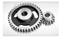
Spur gears: Spur gears are the most common type of gears. They have straight teeth, and are mounted on parallel shafts. Sometimes, many spur gears are used at once to create very large gear reductions. Each time a gear tooth engages a tooth on the other gear, the teeth collide, and this impact makes a noise. It also increases the stress on the gear teeth. To reduce the noise and stress in the gears, most of the gears in your car are helical.
Spur gears are the most commonly used gear type. They are characterized by teeth, which are perpendicular to the face of the gear. Spur gears are most commonly available, and are generally the least expensive.
· Limitations: Spur gears generally cannot be used when a direction change between the two shafts is required.
·
Advantages: Spur gears are easy to find, inexpensive, and efficient.
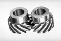
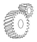
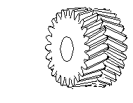
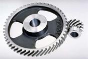
2. Parallel helical gears: The teeth on helical gears are cut at an angle to the face of the gear. When two teeth on a helical gear system engage, the contact starts at one end of the tooth and gradually spreads as the gears rotate, until the two teeth are in full engagement.
Parallel helical gears
Herringbone gears
(or double-helical gears)
This gradual engagement makes helical gears operate much more smoothly and quietly than spur gears. For this reason, helical gears are used in almost all car transmission.
Because of the angle of the teeth on helical gears, they create a thrust load on the gear when they mesh. Devices that use helical gears have bearings that can support this thrust load.
One interesting thing about helical gears is that if the angles of the gear teeth are correct, they can be mounted on perpendicular shafts, adjusting the rotation angle by 90 degrees.
Helical gears to have the following differences from spur gears of the same size:
- Tooth strength is greater because the teeth are longer,
- Greater surface contact on the teeth allows a helical gear to carry more load than a spur gear
- The longer surface of contact reduces the efficiency of a helical gear relative to a spur gear
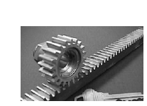
Rack and pinion (The rack is like a gear whose axis is at infinity.):
Racks are straight gears that are used to convert rotational motion to translational motion by means of a gear mesh. (They are in theory a gear with an infinite pitch diameter). In theory, the torque and angular velocity of the pinion gear are related to the Force and the velocity of the rack by the radius of the pinion gear, as is shown.
Perhaps the most well-known application of a rack is the rack and pinion steering system used on many cars in the past
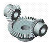
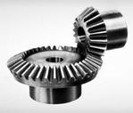
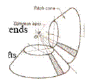
Bevel gears are useful when the direction of a shaft’s rotation needs to be changed. They are usually mounted on shafts that are 90 degrees apart, but can be designed to work at other angles as well.
The teeth on bevel gears can be straight, spiral or hypoid. Straight bevel gear teeth actually have the same problem as straight spur gear teeth, as each tooth engages; it impacts the corresponding tooth all at once.
|
Just like with spur gears, the solution to this problem is to curve the gear teeth. These spiral teeth engage just like helical teeth: the contact starts at one end of the gear and progressively spreads across the whole tooth.
|
|
Straight bevel gears Spiral bevel gears
Hypoid gears (Emerson Power Transmission Corp)
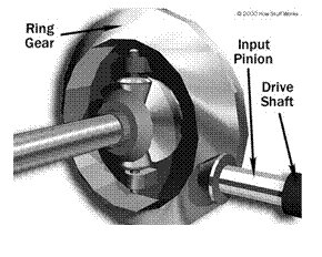
On straight and spiral bevel gears, the shafts must be perpendicular to each other, but they must also be in the same plane. The hypoid gear, can engage with the axes in different planes.
This feature is used in many car differentials. The ring gear of the differential and the input pinion gear are both hypoid. This allows the input pinion to be mounted lower than the axis of the ring gear. Figure shows the input pinion engaging the ring gear of the differential. Since the driveshaft of the car is connected to the input pinion, this also lowers the driveshaft. This means that the driveshaft doesn’t pass into the passenger compartment of the car as much, making more room for people and cargo.
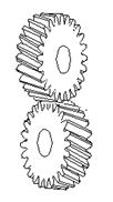
Neither parallel nor intersecting shafts: Helical gears may be used to mesh two shafts that are not parallel, although they are still primarily use in parallel shaft applications. A special application in which helical gears are used is a crossed gear mesh, in which the two shafts are perpendicular to each other.
Crossed-helical gears
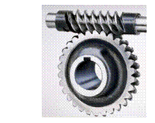
Worm and worm gear: Worm gears are used when large gear reductions are needed. It is common for worm gears to have reductions of 20:1, and even up to 300:1 or greater.
Many worm gears have an interesting property that no other gear set has: the worm can easily turn the gear, but the gear cannot turn the worm. This is because the angle on the worm is so shallow that when the gear tries to spin it, the friction between the gear and the worm holds the worm in place.
This feature is useful for machines such as conveyor systems, in which the locking feature can act as a brake for the conveyor when the motor is not turning. One other very interesting usage of worm gears is in the Torsion differential, which is used on some high-performance cars and trucks.