Fast n Furious

Fast n Furious
mechanical engineers can become a mechanic ,software engineers cannot become a software....

Mar 29, 2012

Flying Windmills Alternative Energy

 Is wind-power energy probably difficult to be directly implemented for batteries of electric cars due to huge electric energy resulted by wind? However, I believe that sooner or later, outstanding engineers will think of conversing huge electricity of wind into proportional electricity for automotive. I am waiting for this. I am so glad for all progress of global technology! Let's talk about windmill!
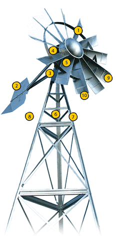
Probably You have ever seen or heard about the windmill / wind turbine in the fields of wheat in Europe, in the pages of the home, or in the ocean, but now wind power engineers are trying to bring it to an altitude windmills 15000-30000 feets in the air . Taking advantage of 1% of jet-stream wind energy, enough energy can be created advantageously for mankind on earth.


Farm Windmills on the Air:

Sky Wind Power as energy company based in San Diego is building a Flying Electric Generator like a kite weighing 1100 pounds, which it can produce electricity at a very low cost of just 2 cents (dollar) per kilowatt hour (kwh) and it was flown at an altitude of 15,000 and 30,000 feet . Four rotors at points-shaped frame of the letter "H" wbeing able to carry his platform floating in the air like a kite. Electricity created by the rotor-spinning rotor that was sent to earth through aluminum cables tethered to his frame.


Sky WindPower, Flying Farm, Flying Electric Generator

Sky WindPower hopes someday to build a windmill farm to fly.Proposal nicknamed FEGs (Flying Electric Generators) will menmpati airspace area of 200 square miles. Turbines are made of aircraft materials consist of rotor-rotor diameter of 130 feet and weighs 45,000 pounds. FEGs it will function like a helicopter while flying, powered from the earth station until then began to collect wind energy. Vertical stabilizer on FEGs will adjust the rotor at different angles to balance its platform and optimize the speed of the wind.


Helium Balloons Producing Electricity:


Cannadian company, Magenn Power has built Magen Power Air Rotor System (MARS), a helium balloon that contains a rotating wind generator on a horizontal axis and sends an electric current through a cable that can be directly utilized, stored in a battery, or passed to electric transmission lines. MARS flown at lower than FEGs, between 600-1000 feet, and works at speeds from 4 mph to more than 60 mph (miles per hour).


Kite Producing Electricity:

Another idea came from Dr. Wubbo Ockels of the Delft University of Technology in (Netherlands).


This technology is very promising where the materials used are not expensive and its potential to create a very large energy, much less known that the strength of winds at a height in the air hundreds of times more powerful than on the mainland. These kites produce power by pulling a generator at the earth station, which rolls back a collection of the kite when it reaches its maximum height. Also unlike the land windmill, this technology also does not need large area to be operated.


This fantastic kite has an area of 10 square meters and it is capable of generating electricity through a generator of 10 kilowatts (enough for 10 homes). And it is currently being developed in experiments with 50 kilowatt kite and a kite-powered line of 100 megawatt-called "Laddermill" . exploiting that very huge electricity is expected to supply energy to 100,000 homes!
Kite is linked to be lined and it plays in a loop which it creates energy and electrical currents created are sent to earth via a cable along 30,000 feet.

Mar 27, 2012

Jet Stream Ram Air Wind Turbine


In earlier posts I have mentioned that a turbine capable of harvesting the energy of jet streams would probably be better for newspaper headlines than for an economical approach to wind electricity, since it would probably be cheaper and more effective to build several smaller low altitude turbines than a single monster that could tap into the jet streams. But it got me to realize that there are no jet stream turbines on the Salient White Elephant. This is Salient, to be sure, but is it White Elephant? Certainly not! And already I can hear not a little hubbub from the Canadian Parliament behind me patting their tables and gushing heah heah! So let’s just round things out with a couple of jet stream turbines before tensions run too high and one of the hairs on the head of the Right Honourable Stephen Harper springs noticeably out of place, shall we?
Jet Stream Ram Air Wind Turbine
For some reason, I’m usually biased toward using suction rather than high pressure in my flow accelerator ideas. But one advantage of using ram air pressure in the machine proposed here is that it would keep the long fabric tube inflated. This is very significant of course, since one of the biggest challenges in designing an airborne turbine is keeping weight to a minimum. Using high pressure might eliminate any rib-like supporting structure that would otherwise be required for the tube. I guess you’d have to stabilize the fabric tube by attaching it to the tethering cables at various intervals, but who knows… maybe somebody can design a way around this requirement.

Triple Tethered Variation

Jet Stream Ram Air Wind Turbine, Triple Tethered Variation

Multiple Blimps Variation

There are many variations of the ideas proposed here, but let me discuss one in particular. This idea emphasizes a technique I’d like to use to bring these pie-in-the-sky airborne turbines a little closer to feasible. Imagine eight blimps. Each is tethered by at least three cables to keep the blimps from moving around too much. An aerial view would reveal that the blimps are situated at the vertices of a gigantic octagon. It is important to note that the “diameter” of the octagon is far from insignificant. I can’t give you a number… maybe two or three football fields? Each blimp has a parachute and a high pressure tube, just as described above. All of the high pressure tubes converge at the center of the octagon, where they connect to a single larger high pressure tube that takes the jet stream wind down to the ground.
What’s so great about this variation? Well… let me first list what I believe may be the salient objectives of airborne turbine design:
  • If possible, no moving parts in the air.
  • If possible, no fiberglass, electrical cable, gearboxes, drive shafts, or electrical generators in the air. (Ever notice how the components of a wind turbine that have to do with mechanical and electrical power are about the most dense (heaviest) things known to engineering kind?!)
  • MINIMIZE WEIGHT, MINIMIZE WEIGHT, MINIMIZE WEIGHT!!!!!!!!!!!
So the idea here is that instead of having eight different tubes, we attempt to minimize weight by having a single large tube carry wind from the jet stream to the ground. This is desirable because the really long distance is from the jet stream to the ground. Once at the center of the jet stream octagon, it isn’t much further to the blimps. So could we use this trick to reduce the overall weight of the machine?
Well, whether this trick will work or not… I think you see my point. What is needed is a kind of linear programming style optimization that minimizes weight of fabric per kilowatt of capacity.

Can We Really Reach the Jet Stream?

No. The jet streams are like 30 to 40 thousand feet off the ground. (The cruising altitude of jet airplanes!) So we can’t reach the jet stream with the design proposed in this post. But we can certainly reach a higher altitude than today’s state of the art wind turbines! If you want to see a more practical configuration that uses the principles described in this post, check out the Practical Artificial Pressure Differential Wind Turbine.

Mar 26, 2012

Carbon Fiber-Materials


    Carbon fiber is a relatively new material to robotics. However, it has already become a very important material, making new robots possible that were not possible before.
    Strength
    Carbon fiber has a very high strength to weight ratio, meaning that for another material of the same weight, it is likely to be much stronger. But carbon fiber is a fibrous material, meaning that the fibers are all aligned in a single direction. This can affect strength if used improperly.
    Because the fibers are aligned, carbon fiber has different strength amounts - depending on the direction that force is applied at. For example, rope is very strong if you pull, but very weak if you push. Carbon fiber is very strong in both compression and tension, but is much weaker in bending (force from the side). It is like trying to break a stick - breaking it at the center is much easier than by pulling it from the sides. So when using carbon fiber, make sure all force is only applied longitudinally.
    Carbon Fiber Low Weight Properties
    Weight
    Carbon fiber is extremely lightweight for its strength - this is why it is now very common now in hobby RC aircraft and micro-air robots. Some micro-air robot craft were not even possible before carbon fiber! Before it became popular, balsa wood was the prevailing lightweight structural support material. If you are currently using balsa, you should probably switch. Really an amazing material. I used to do research for the CMU NanoRobotics Laboratory and carbon fiber outperformed all other materials for my microrobotic applications.
    Carbon Fiber Applications
    Other Applications for Carbon Fiber
    Carbon fiber is sold in various very affordable shapes: round tubes, square tubes, flat sheets, retangular bars, and a few others. Tubing is usually used for structural support. The flat sheets are used for ant weight battle bot armor and other chassis covering. I have use rectangular carbon fiber bars to make 4-bar linkages (shown in the image at the top of this page). The shape you use will be dependent on how you expect the force to applied, amount of force, and your attachment method.
    Carbon fiber has other useful properties as well. Since it is non-metallic, it can be used in applications where metal would interfere with sensors. Medical MRI's (magnetic resonance imaging) machines use very strong magnetic fields, preventing things like surgery robots to be used inside of them. But if you make the robot out of something non-magnetic, such as carbon fiber, that would no longer be a problem. Carbon fiber is already used to make backing boards to tie patients down for things like CAT scans and X-Rays. Why? CAT scan machines detect radiation emission from a radioactive isotope injected in to you. X-Ray machines detect radiation reflected back from you. Metal however attenuates (blocks) radiation, making the sensors useless. Why do you think Superman can't see through lead?


    Working with Carbon Fiber
    Working with carbon fiber is very easy. You can basically work with it the way you work with wood. But being a fibrous material, you have to be very careful ofsplintering - taking a little practice to master. There are several tools you should keep around for when you work with carbon fiber. Remember, if you choose the wrong tools, your subjecting your carbon fiber to splintering.
    Jewelers' Saw for Carbon Fiber
    Jewelers Saw can be bought at various jewelry and hobby stores. What makes it good is that it is fine toothed and designed for precision cutting work. If you have a hacksaw with a fine toothed blade that should work. The blade must be sharp and with no damage.
    Snips for Carbon Fiber
    A pair of fine cutting snips for cutting is also highly recommended. These are good for cleaning up a saw cut that has a few remaining fibers that escaped your wrath. For the very thin rectangular carbon fiber, snips can be used instead of a jewelers' saw. Again, make sure this tool is extremely sharp.
    Drilling for Carbon Fiber
    For drilling you can use normal drill bits. But if you just drill straight out without first preparing the carbon fiber you will quickly notice splintering and breaking at the drill point. I have tried taping over the area I want to drill to get reasonable results. But you probably also want to paint the area over with a plastic buffer (made from a cheap plastic putty) or soaking the area over in superglue (the running type that can soak in between the fibers) to prevent damage from the drill chuck.
    Make sure your drill bit is really sharp (new bits or diamond tipped bits work best) because any roughness will pull at the fibers instead of cutting - hence causing damage. Make sure you drill slowly. After drilling, you want to file away any splintering with fine grain sandpaper and/or scotchbrite. Then coat the finished area with a layer of superglue and let dry. The superglue will hold the loose fibers together and prevent any future damage. Use this method of filing and glueing for when you cut/saw carbon fiber too.
    Attaching Carbon Fiber
    Attaching pieces of carbon fiber together (or to other materials) can be a little tricky. For attaching sheets and plates it is somewhat easy. You can drill a hole in each and bolt them together. And/or use epoxy or fiberglass resin which you can normally find in repair kits (such as for boats at boating supplies stores). Make sure you work all the air bubbles out of the epoxy mix while it is drying (bubbles are weak spots). For really serious bonds, try an epoxy called Plexus. I have not used it myself, but I hear it is good. For attaching rods together it gets a little tricky. The bolting method using screws works. There are also special plastic connectors sold at various angles where you can just attach both ends of your carbon fiber rods together.
    'Molding' with carbon fiber is somewhat complicated, and since I have never done it myself, I wont go into much detail. But basically you buy a bunch of paper thin sheets of it and glue it all together over a mold to become this cool looking custom shaped shell. You will have to do temperature control and layering and all this other complex stuff. Will probably make an interesting alternative to the advantages of vacuum forming if you are willing to attempt it.
    Safety
    I am actually shocked at how little safety has been paid attention to online for carbon fiber. A Google search for carbon fiber safety tips yielded zero useful results for me. I am no expert on carbon fiber safety, so I will just go through the common sense stuff. So first, lets talk about the dangers of carbon fiber. Carbon fiber is exactly what the name suggests, extremely thin strong fibers. Basically light weight needles capable of jabbing into your skin or worse - capable of becoming airborne and jabbing into your lungs and eyes, etc. Coughed up blood, anyone? You get the idea.
    Apparently some people are even allergic to some degree and get skin reactions from it. "It's a skin reaction that looks like a really bad sun burn and itches like a mother." If you plan to saw or drill carbon fiber, expect copious amounts of fine particles to become airborne.
    Carbon Fiber Safety
    Now protection for carbon fiber should be obvious for you. Above anything else you want a basic $1 face mask for breathing. Probably you want to do this outside with air flow as well. This has been sufficient for me to work with it. But if you require more, like if you are allergic to it, then eye protection goggles, and even a Tyvek suit (such as for HAZMAT stuff, shown in the above image) will work.
    Additional Carbon Fiber Notes
    UV light can and will break down carbon fiber over time. UV top coat is advised, and gives the parts that nice shiney finish.
    Carbon Fiber Tape
    Carbon fiber tape looks neat, but I just have not found a use for it yet. Maybe for wings?

Mar 25, 2012

TURBO JET STREAM WINDMILL


Theory of Operation:
Under the water's surface there are aerobic bacteria feeding on organic matter, which consumes large quantities of oxygen. When this oxygen becomes depleted, hydrogen sulfide gas is produced as a byproduct. This causes the water to turn black and a foul odor follows, similar to rotting eggs. When you use a Superior Windmill the water stays aerated preventing this problem from happening. You can be assured that by using our single diaphragm (JET STREAM) pump, or our double diaphragm pump (TURBO JET STREAM), the oxygen level in your water remains high and your water clean.
Aeration systems are ways of adding air to water in order to replenish its oxygen levels. The more air that is pumped into the water the better the circulation, thus reducing chances of bacteria build up and stratification. This process is most commonly used with non-free flowing bodies of water such as lakes, ponds, farm dugouts, reservoirs etc...
The oxygen that is pumped into the water is extremely effective in breaking down organic matter and sludge (beneficial bacteria that culminates at the bottom).

How Aeration Systems Impact Water Quality
Aeration systems are useful all year round in order to keep bodies of water healthy. The Canadian Department of Agriculture and Agri-Food Canada have done enormous research on this topic to assist farmers in particular with the water quality of their farm dugouts.
View this flash demonstration published by the Canadian Government on pond aeration.
Specifications:
    Tower
    • Tower height is 12 foot or 20 foot
    • Stance of base is 61" for the 12 foot tower or 97" for the 20 foot tower

    Turbine
    • Upwind turbine is 70" in diameter

    Construction
    • Fan blades, hub, tail and stand are manufactured from galvanized steel.
    • The hub assembly and compressor are pre-assembled at the factory to assist with ease of installation and proper operation of the moving parts.

    Compressor
    • We use a direct drive system with a diaphragm stroke of 9/16" in the transmission
    • Over-speed is controlled by the turbine furling out of the wind as required

    Weights
    • Jetstream Pump = 38 lbs
    • Turbo Jetstream Pump = 49.5 lbs
    • Blade = 47 lbs
    • Tower 12' = 193 lbs
    • Tower 20' = 271 lbs

    Performance Specifications
    • Max air psi207 Kpa (30 psi)
    • Volume of Air Produced
    • Jetstream Single cylinder pump
      • 90 cfH or 1.5 cfm @ 15 Kph (9 Mph)
    • Turbo Jetstream Dual cylinder pump
      • 180 cfH or 3.0 cfm @ 15 Kph (9 Mph)
Note Package Contents:
  • The Jet Stream Package includes:
    • One single diaphragm compressor
    • 70” turbine
    • 12 or 20 foot tower kit
    • 3 four-foot ground rods
    • 50’ of PVC 300 psi air hose and fittings
    • One 9” air diffuser
    • Installation manual and hardware
  • The Turbo Jet Stream Package includes everything in the Jetstream Package except:
    • One dual diaphragm compressor instead of the single diaphragm model
  • The Superior Plus Turbo Jet Stream Package includes everything in the Turbo Jetstream Package plus:
    • Dual Diffuser Package
    • Manifold and fittings
    • 100’ of PVC 300 psi air hose and fittings
    • One more 9” air diffuser
    • One inline pressure gauge
    • Freeze Control Kit

Features
There are two main ways to aerate your ponds, lakes or dugouts…By Surface or Diffused Aeration
Surface Aeration - are systems that come in the form of Fountains or Jets and are primarily used to produce surface level oxygen in the water. They splash the surface and help control top level algae and weeds, they do not aerate down to the bottom. This type of aeration looks attractive but as research indicates, is one of the most ineffective ways to keep your water healthy. Oxygen never gets to the bottom of the water where it is needed to organically break down the sludge that constantly enters the water and sinks down.
Diffused Aeration – are systems where air is pumped into the water and through air diffusers that lie at the bottom of the pond, lake, or dugout. This achieves total pond aeration from the bottom to the top regardless of the depth of the water. These systems are both more effective and economical, for it requires far less energy to push air in a diffused aeration system than it does pushing water through fountains or jets.
By harnessing the wind you can oxygenate and de-stratify your pond. Our “Superior” line of Windmills has been redesigned to provide ample supplemental oxygen levels to improve the health of your ponds, lakes, dugouts or reservoirs. Ideally suited for areas needing aeration without electricity nearby and can be located hundreds of feet away from the water's edge, if necessary to catch more wind.

Superior Windmill Aeration systems will:
  • Help prevent algae and weed growth
  • Help prevent water discoloration
  • Eliminate thermal stratification
  • Reduce the Biological Oxygen demand
  • Reduce the sedimentation rate causing a build up of sludge and muck
  • Improve water clarity and cleanliness
  • Reduce chemical use and costs of chemicals
  • Reduce overall costs of maintaining a healthy pond, lake, dugout or reservoir.
  • Eliminates fish kills and promotes healthy aquatic life
  • Eliminate foul odors
  • Cost no money to operate
Who uses Aeration Systems
From farm dugouts and septic systems to small and multi-acre sized residential ponds. SUPERIOR WINDMILL is the clear choice for aeration systems and installation. Proper aeration of the water source can prevent the release of sediment-bound nutrients, and reduce corresponding algae blooms. In addition, supplemental aeration can facilitate decomposition of organic material, and minimize oxygen-related stress on fish. This is particularly critical during the summer months, when water temperatures are capable of holding less oxygen. It is also critical in the winter months for its keeps these bodies of water from totally freezing over – critical to the health of any body of water.
CROP and CATTLE FARMERS
Many farmers have water dugouts throughout their property allowing for convenient and cost effective irrigation of crops and clean water supply for grazing cattle and horses. Superior Windmill aeration systems helps farmers keep their animals safe from disease and crops healthy by keeping a farm's water sources clean. Studies have shown that when cattle drink healthy water they gain more weight.
FISH HATCHERIES
Aeration systems dissolve oxygen into water and the more oxygen that is present the healthier the aquatic life will be. Fish Hatcheries need additional oxygen in their water for two main reasons. The first is to oxidize or burn up the additional amounts of pollution created by the large amounts of fish waste. Second is to give the fish more oxygen to live so that all the fish get ample supply of this resource ensuring that both the strong and the weak survive. Limiting the amounts of fish kill can mean the difference between profit and loss in these hatcheries.
CORPORATE OR RESIDENTIAL PONDS and LAKES
Residential areas, corporate parks or condominium communities are often complaining about the water clarity and odor in their local ponds. Superior Windmill's design of a low maintenance, high volume aeration system that is decorative, energy efficient and noise free is the perfect solution. The water oxygenation results in the elimination of bad odors and increases water clarity in no time. This solution is extremely effective for ponds of any size from 1/2 acre right up to small lakes 5-10 acres.
DRINKING WATER RESERVOIRS
For small drinking water reservoirs Superior Windmill has designed diffusers to improve water quality in various sized reservoirs. A properly designed submersed air diffusion system can effectively circulate large areas of water with minimal to no energy requirements. In addition to the submersed aeration systems, Superior Windmill offers the winterized kit ensuring you that your water is safe to drink during all four seasons.
GOLF COURSES
Courses are deploying aeration systems to help oxidize or burn up the waste that is being created by the ducks and other birds that are making their homes in these recreational paradises. Without adequate aeration these scenic courses can begin to smell like garbage dumps. The smell combined with the odd looking color of the water has driven many course owners to install Superior Windmill Aeration Systems.
WILD LIFE and ENVIRONMENTAL GROUPS
These associations are discovering that these systems can be of great benefit in maintaining healthy water sources and supplies for their inhabitants. Having limited resources these federations require a cost effective, reliable and low maintenance solution to keeping their ponds and lakes healthy. They are turning to Superior Windmill.


Mar 22, 2012

First INtelligent Extinguisher (FINE) Robot

FINE is an intelligent fire extinguisher designed to effectively fight against a domestic fire. It can be easily used as a traditional fire extinguisher by an individual. Also, it can alert the fire fighters if a fire takes place when nobody is at home and starts putting out the fire automatically until the fire fighters involves with the situation. This compact product contains an infrared thermometer to sense flames, a rolling base, a container of powder and collision sensors to evade obstacles. It comprises a usual smoke detector and moves towards the fire to pulverize the powder into the core of the fire.


Mar 21, 2012

Frictionless Compressors


Are they right for you?

Compressors that run on frictionless bearings are an enticing prospect. Dan Foss Turbocor, Inc. is now marketing a line of compressors that use magnetic bearings to provide essentially frictionless operation. These compressors have been on the market for about three years, and now McQuay International is incorporating the compressors into their new line of frictionless chillers.

Using innovative technology that levitates the compressor shaft in a magnetic field, the compressors operate without metal-to-metal contact, making them more efficient, and eliminating the need for an oil management system. Turbocor has recently received three prestigious awards for this design: the ASHRAE/AHR Expo "Energy Innovation" Award in 2003, the Natural Resources Canada's Energy Efficiency Award in 2003, and the U.S. Environmental Protection Agency’s Climate Protection Award in 2004. 


How are they different?
Here are some of the features, benefits, and concerns to help you decide whether frictionless compressors (or McQuay’s frictionless chillers) are right for you. Each feature is discussed in more detail below.

· Magnetic bearings.
· Oil-free design.
· Low noise Level
· VFD control.
· Soft start.
· Smaller and lighter than conventional compressors.
· Uses a centrifugal compressor.

Magnetic bearings
A digitally controlled magnetic bearing system, consisting of both permanent magnets and electromagnets, replaces conventional lubricated bearings. The only rotating part—the compressor shaft—is levitated and held in place by magnetic bearings, eliminating metal-to-metal contact, essentially eliminating friction.

Four positioning signals, sampling six million times per minute, hold the levitated position to within 0.00005” of center. The advantages of this technology include:
  • No friction. This can improve energy efficiency by 2-4%.
  • No metal-to-metal contact, therefore less wear on moving parts. Turbocor claims that maintenance costs are about half what they are for conventional technology.
  • The frictionless bearings, in conjunction with variable frequency drive (VFD) control, allow the shaft to spin at high speeds (up to 48,000 RPM) and give good speed control.
  • Very little vibration. Because of no physical contact, vibrations are small and tend to be self-dampened. 
The magnetic bearing system, however, is more expensive and it takes some energy to operate the system. The levitation system on current models uses approximately 180 watts, or about 0.5% of the operating energy. Contrast this to 2-4% for conventional bearings, along with a lubrication system that (according to Turbocor) can use up to 10,000 watts.

Oil-free design
The biggest benefit to eliminating oil from the system is that it eliminates the need for a lubrication system, which can include oil pumps, sumps, oil separators, heaters, coolers, etc. In comparing the costs of two proposed systems, it important to consider lubrication in estimating both the capital and operating costs. The other disadvantage of having oil in the system is that it can reduce the effectiveness of heat transfer in the coil. The effect of this, however, is small. While the Turbocor website suggests that heat transfer effectiveness can be reduced by 15% or more by the presence of oil, this will most likely translate into a somewhat smaller effect on overall system efficiency.

Low noise level
The Turbocor compressors, by all reports, make significantly less noise than the comparable screw compressors. What noise there is tends to be high frequency, which is relatively easy to attenuate.

VFD control
The big potential savings of this system comes from the integrated variable frequency drive. This provides good speed control, allowing the system to run up to 48,000 RPM and (because there is no friction in the motor) it can also operate efficiently at low loads.

In addition, the compressor has automatically controlled inlet guide vanes that unload further in low-load conditions. These features give the system an excellent integrated part-load value (IPLV) rating. Many chillers in HVAC applications are running at part load a vast majority of the time, making them an excellent application for the frictionless system.

Turbocor claims that they have achieved an IPLV rating as low as 0.375 kW/Ton, compared to 0.63 kW/Ton for the Turbocor at full load, and 0.5 kW/Ton being considered a very good rating. Herein lies the key to a successful application of Turbocor. If the chiller will be operated at part load a good proportion of the time, a frictionless chiller is worth considering.

Soft start
An added benefit of having the integrated VFD is that the motor has a built-in soft start. Turbocor uses a unique method of soft start that ramps the motor up gradually, making inrush current effectively the full load current. On Turbocor’s website, they list the inrush current as 2 amps, or 5 amps in some places, meaning, presumably, that the ramping up process starts with this very low current. It is not clear how this information is useful, since the information about inrush current is generally used for sizing circuit breakers. The breaker would simply have to be sized for the full load amperage.

Small and Lighter
Using permanent magnets in the motor, rather than electrical windings as in an induction motor, reduces the size and weight significantly. In addition, by running the shaft at high speeds, they are able to use a smaller, lighter, shaft. According to the manufacturer, the Turbocor compressors, at 265 lbs., are one-fifth of the weight and half the size of an equivalent conventional compressor.

Uses a centrifugal compressor
Centrifugal compressors tend to be more efficient than screw or scroll compressors, and take advantage of speed control more effectively, but they are usually only available in larger sizes. By using the smaller shaft, they are able to take advantage of the centrifugal compressor technology in a smaller size than is normally available.


Is it a Right Choice - Baby?That depends. The design of these compressors is clearly innovative, elegant, and efficient, and all indications are that it is a quality product. The idea of using magnetic bearings is provocative, but it turns out that this feature in itself is rarely enough to justify considering the 50-70% price premium you are likely to pay for a frictionless compressor. However, with associated benefits, it may be well worth considering.

Remember to take into consideration not having to include an oil management system, and perhaps easier and quicker installation. Certainly in an application where the chiller runs at part load much of the time, such as in many HVAC applications, the efficiency may be much better. In that case, the IPLV rating will be a better indication of the relative performance than the full-load rating, but it will probably be worthwhile to have an engineer do a full analysis of the relative costs based on your particular application. The more your chiller will be running at part load, the more attractive this product will be. Reduced maintenance costs may tip the scales in favor of going frictionless.

Mar 20, 2012

FDM

Fused Deposition Modelling :
Fused deposition modeling (FDM) is an additive manufacturing technology commonly used for modeling, prototyping, and production applications. The technology was developed by S. Scott Crump in the late 1980s and was commercialized in 1990.


Process:

FDM begins with a software process, developed by Stratasys, which processes an STL file (stereolithography file format) in minutes, mathematically slicing and orienting the model for the build process. If required, support structures are automatically generated. The machine dispenses two materials – one for the model and one for a disposable support structure.
The thermoplastics are liquefied and deposited by an extrusion head, which follows a tool-path defined by the CAD file. The materials are deposited in layers as fine as 0.04 mm (0.0016") thick, and the part is built from the bottom up – one layer at a time.


FDM works on an "additive" principle by laying down material in layers. A plastic filament or metal wire is unwound from a coil and supplies material to an extrusion nozzle which can turn the flow on and off. The nozzle is heated to melt the material and can be moved in both horizontal and vertical directions by a numerically controlled mechanism, directly controlled by a computer-aided manufacturing (CAM) software package. The model or part is produced by extruding small beads of thermoplasticmaterial to form layers as the material hardens immediately after extrusion from the nozzle. Stepper motors or servo motors are typically employed to move the extrusion head.


Several materials are available with different trade-offs between strength and temperature properties. As well as acrylonitrile butadiene styrene (ABS) polymer,polycarbonates, polycaprolactone, polyphenylsulfones and waxes. A "water-soluble" material can be used for making temporary supports while manufacturing is in progress, this soluble support material is quickly dissolved with specialized mechanical agitation equipment utilizing a precisely heated sodium hydroxide solution.
The term fused deposition modeling and its abbreviation to FDM are trademarked by Stratasys Inc. The exactly equivalent term, fused filament fabrication (FFF), was coined by the members of the RepRap project to give a phrase that would be legally unconstrained in its use. It is a new model.


Commercial Applications:
FDM, a prominent form of rapid prototyping, is used for prototyping and rapid manufacturing. Rapid prototyping facilitates iterative testing, and for very short runs, rapid manufacturing can be a relatively inexpensive alternative. 
FDM uses the thermoplastics ABS, ABSi, polyphenylsulfone (PPSF), polycarbonate (PC), and Ultem 9085, among others. These materials are used for their heat resistance properties. Ultem 9085 also exhibits fire retardancy making it suitable for aerospace and aviation applications.
FDM is also used in prototyping scaffolds for medical tissue engineering applications.