Fast n Furious

Fast n Furious
mechanical engineers can become a mechanic ,software engineers cannot become a software....

Jun 30, 2013

Bearings

bearing is a machine element that constrains relative motion between moving parts to only the desired motion. The design of the bearing may, for example, provide for free linear movement of the moving part or for free rotation around a fixed axis; or, it may prevent a motion by controlling the vectors of normal forces that bear on the moving parts. Bearings are classified broadly according to the type of operation, the motions allowed, or to the directions of the loads (forces) applied to the parts.


Parasitic Power Losses in Hydrodynamic Bearings

Parasitic frictional losses in machines result in wasted energy and the generation of heat, which affects the life of materials, including the lubricant. A significant portion of total fluid film bearing losses in high-speed turbomachinery may be consumed simply in feeding oil to the bearings.
At surface speeds below roughly 10,000 ft/min, these extraneous parasitic losses are generally less than 10 percent of those of the oil-film frictional losses. For higher velocities, however, these losses increase rapidly with surface speed and can reach 25 to 50 percent of the total bearing loss in large turbine-generators and related machinery. This article discusses parasitic frictional losses in turbo machinery and suggests means for their reduction.


Sources of Parasitic Losses 
Parasitic losses for both journal and thrust bearings (Figures 1 and 2) can be assigned to two categories: through-flow loss simply caused by the lube oil’s passage through a bearing, and surface drag between the lube oil and rotating surfaces. Due to larger diameter and large surface area, these losses are generally greater in thrust bearings.
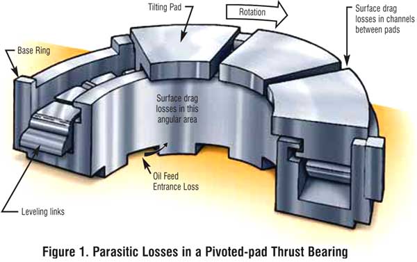
Through-flow Loss. These losses result from three sources: acceleration of the oil as it enters feed ports, influx and outflux of lubricant to and from feed grooves, and discharge of the lubricant from the bearing (leakage). Through-flow losses for a pivoted-pad thrust bearing can be assigned to the following sources (Figure 1):
  1. One single velocity head loss for oil entering at the shaft surface velocity. This loss is associated with the flow of the oil feed as it enters under the base ring, makes an abrupt turn, and is brought to the bulk oil velocity between the shaft outside diameter and the inside diameter of the base ring.
  2. One single velocity head loss, calculated at the mean thrust runner diameter, for the oil as it passes into the channels between the tilting pads and into the bearing oil film.
  3. Approximately 25 percent of discharge oil is assumed to be splashed onto the thrust runner to be reaccelerated at the runner’s outside diameter. This action is not typically encountered in conventional journal bearings.

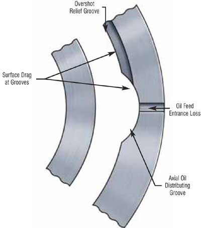
Figure 1. Parasitic Losses in a Pivoted-pad Thrust Bearing
Referring to Figure 2, a plain cylindrical axial-groove journal bearing introduces a total parasitic loss of 1.5 velocity heads (calculated at the shaft surface velocity). This results from acceleration of the feed oil as it enters into the turbulent vortex in the feed groove and then further accelerates as it enters the bearing oil film itself. In pivoted pad journal bearings, on the other hand, vortex action and churning in the square-sided cavity between pads offers more resistance to entering feed oil.
Surface Drag Losses. Power loss from fluid friction drag on wetted shaft and thrust collar areas follows the general turbulent relation for hydraulic drag in channels where frictional loss is related to the dimensionless Reynolds number. For circular annular spaces around a journal, and for overshot internal grooves, as in the upper half of some journal bearings, the estimate of drag coefficient should be increased by 30 to 40 percent These losses would be reduced by appropriate draining of the housing to avoid fully-flooded operation.
Reducing Parasitic Losses
Several strategies may be employed to minimize parasitic losses in high-speed bearings. The simplest is to reduce the oil feed volume. A method that nearly eliminates the through-flow losses in fixed-pad bearings is discussed in the next section. For pivoted shoe bearings, feeding the oil directly to the leading edge of each bearing pad is an attractive method for decreasing parasitic power losses.
Decreased Loss with Partially Filled Grooves.When the oil feed rate drops to the extent that internal grooves in a bearing are not completely filled with oil, the parasitic drag loss in the groove also drops, frequently to a negligible level.

Figure 3. Decrease in Power Loss in a 27-inch
O.D. Tapered Land Thrust Bearing Partially Filled
Figure 3 illustrates this point for a 350-square inch tapered-land steam-turbine thrust bearing operating at 3,600 rpm, wherein a step drop in power loss was encountered with decreasing oil flow. As the design oil feed was gradually reduced, at 166 gpm the total power loss in the bearing dropped from 800 to 473 hp. At this point, the back pressure dropped in the feed grooves with simultaneous elimination of through-flow loss for the entering oil.
Combined with observation of low loss in cavitated hydrodynamic oil films themselves, surface drag losses appear to become negligible for all partially filled zones within a bearing.
Leading Edge Feed Grooves. Several pivoted-pad bearing designs use sprays or channels to feed oil directly to the leading edge of each thrust pad in a bearing cavity otherwise empty of oil. These arrangements avoid essentially all surface drag losses which would otherwise be encountered by rotating surfaces immersed in oil as well as portions of through-flow losses. Such designs are offered primarily for the surface speeds above that encountered in journal bearings with diameters approximately 10 to 12 inches operating at 3,600 rpm. For lower surface velocities, parasitic power losses become so low as not to warrant the extra cost and complexity with specially directed feed.
In high-speed bearings, leading edge oil feed grooves provide significant benefits. Oil flow rates can be as much as 60 percent lower with power loss down 45 percent. While a variety of lubrication flow arrangements, design and operating factors exert an influence, the resulting bearing temperature may be reduced by 16 to 35°F.

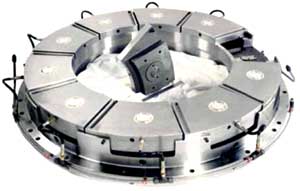
Figure 4. Pivoted Pad Thrust Bearing with
Leading Edge Oil Feed Grooves and Oil Lift
Pockets (Courtesy Kingsbury, Inc.)
As a surprising factor, reversing the rotation to place the oil feed groove at the trailing edge of each pad still provides satisfactory operation of a pivoted pad journal bearing at moderate speeds. This suggests that hot oil is still carried over from one pad to the next, and that absence of bulk oil from the bearing cavity is likely the major benefit to be realized from directed lubrication.
As bearing surface speeds range above approximately 10,000 ft./min., significant parasitic power losses may be encountered. At 30,000 ft./min., these losses may range up to half of the total power loss experienced in a bearing – equal to the power loss in the hydrodynamic load-supporting oil film itself. The following are factors to consider for minimizing parasitic frictional losses and achieving lower bearing temperatures:
  1. Limit oil feed rate to the minimum required for reliable bearing operation.
  2. Blend the shape of oil groove entrance ports and groove walls to minimize vortex flow restrictions.
  3. Minimize unessential oil-wetted areas on rotating journal and thrust surfaces.
  4. Minimize splashing of discharge oil onto rotating surfaces.
  5. Utilize directed lubrication with leading edge grooves to feed tilting-pads.

Jun 27, 2013

Mechanical Devices

Chaff Cutters


chaff cutter is a mechanical device for cutting straw or hay into small pieces before being mixed together with other forage and fed to horses and cattle. This aids the animal's digestion and prevents animals from rejecting any part of their food.


Chaff and hay played a vital role in most agricultural production as it was used for feeding horses. Horses were extensively used in farming operations until they were replaced by tractors in the 1940's.


Chaff cutters have evolved from the basic machines into commercial standard machines that can be driven at various speeds and can achieved various lengths of cuts of chaff with respect to animal preference type. New chaff cutter machines include portable tractor driven chaff cutter - where chaff cutter can be in the field and load trolleys (if required).


Chaff Cutting Machine ( SP 10 PLAIN ):
 
Hand cum power operated, Covered fly wheel, Feeding tray,
Slide rail for motor, Motor pully, Machine pully, Handle, Grinder.
But without NEUTRAL & REVERSING arrangement.
R.P.M. MAX : 150
H. P. REQD : 1 : 2 H. P.
CAP.KGS. PER HOUR : 150
BLADES ARNGT : 2
 
Chaff Cutting Machine ( SP 10 SPECIAL ) :
 
Hand cum power operated, Covered fly wheel, Feeding tray,
Slide rail for motor, Motor pully, Machine pully, Handle, Grinder.
But without NEUTRAL & REVERSING arrangement.
Above machine but with NEUTRAL & REVERSING arrangement.
R.P.M. MAX : 200
H. P. REQD : 1 : 2 H. P.
CAP.KGS. PER HOUR : 200
BLADES ARNGT : 2
Chaff Cutting Machine ( SP 14 SG ) :
 
Power operated, Covered fly wheel from top as well as bottom,
feeding tray, Slide rail for motor, Motor pully, Machine pully &
Grinder.
R.P.M. MAX : 300
H. P. REQD : 3 : 5 H. P.
CAP.KGS. PER HOUR : 300
BLADES ARNGT : 3
Chaff Cutting Machine ( SP 14 SGDB ) :
 
Power operated, Covered fly wheel from top as well as bottom,
feeding tray, Slide rail for motor, Motor pully,Machine pully &
Grinder. Above machine with Downward Blower arrangement.
R.P.M. MAX : 300
H. P. REQD : 3 : 5 H. P.
CAP.KGS. PER HOUR : 300
BLADES ARNGT : 3
Chaff Cutting Machine ( SP 25/4 BLADED ) :
Chaff Cutting Machine ( SP 25/4 BLADED ) :
 
Power operated, Covered M. S. Plate Wheel fitted with Steel
blades, Feeding tray, Slide rail for motor & grinder. Machine
Pully, Grinder & Regrinding attachment. Downward blower.
Above machine with 4 Blades arrangement.
R.P.M. MAX : 400
H. P. REQD : 5 : 7.5 H. P.
CAP.KGS. PER HOUR : 800
BLADES ARNGT : 4
 
Chaff Cutting Machine ( SP 30/ 3 BLADED )
Chaff Cutting Machine ( SP 30/ 3 BLADED ) :
 
Power operated, Covered M. S. Plate Wheel fitted with Steel
blades, Large feeding tray, Pressing drum, Complete ball
bearings, Slide rail for Motor & Grinder. Machine Pully, Grinder
& Regrinding attachment. Downward & High level blower.
R.P.M. MAX : 600
H. P. REQD : 7.5 : 10 H. P.
CAP.KGS. PER HOUR : 1500
BLADES ARNGT : 3
 
Chaff Cutting Machine ( SP 30/ 3 BLADED )
Chaff Cutting Machine ( SP 30/ 3 BLADED ):
 
Power operated, Covered M. S. Plate Wheel fitted with Steel
blades, Large feeding tray, Pressing drum, Complete ball
bearings, Slide rail for Motor & Grinder. Machine Pully, Grinder
& Regrinding attachment. Downward & High level blower.
Above machine with 4 Blades arrangement.
R.P.M. MAX : 600
H. P. REQD : 7.5 : 10 H. P.
CAP.KGS. PER HOUR : 1500
BLADES ARNGT : 4
 
Chaff Cutting Machine ( SP 30/ 3 BLADED DB )
Chaff Cutting Machine ( SP 30/ 3 BLADED DB ):
 
Power operated, Covered M. S. Plate Wheel fitted with Steel
blades, Large feeding tray, Pressing drum, Complete ball
bearings, Slide rail for Motor & Grinder. Machine Pully, Grinder
& Regrinding attachment. Downward & High level blower.
with Downward blower only.
R.P.M. MAX : 600
H. P. REQD : 7.5 : 10 H. P.
CAP.KGS. PER HOUR : 1500
BLADES ARNGT : 3
 
Chaff Cutting Machine ( SP 30 DB 4 BLADED ) :
Chaff Cutting Machine ( SP 30 DB 4 BLADED ) :
 
Power operated, Covered M. S. Plate Wheel fitted with Steel
blades, Large feeding tray, Pressing drum, Complete ball
bearings, Slide rail for Motor & Grinder. Machine Pully, Grinder
& Regrinding attachment. Downward & High level blower.
Above machine is 4 Blades arrangement.with Downward
blower only.
R.P.M. MAX : 600
H. P. REQD : 7.5 : 10 H. P.
CAP.KGS. PER HOUR : 1500
BLADES ARNGT : 4
 
Chaff Cutting Machine ( SP 40 ) :
Chaff Cutting Machine ( SP 40 ) :
 
Power operated, Covered M. S. Plate Wheel fitted with 4 Steel
blades, Large feeding tray, Pressing drum, Complete ball
bearings, Heay frame made out of 4" channel, Slide rail for
Motor & Grinder.'C' sec heavy machine Pully, Grinder &
Regrinding attachment. Downward & High level blower.
R.P.M. MAX : 500
H. P. REQD : 15 : 20 H. P.
CAP.KGS. PER HOUR : 3000
BLADES ARNGT : 4
Chaff Cutting Machine ( SP 25/3 BLADED ) :
Chaff Cutting Machine ( SP 25/3 BLADED ) :
 
Power operated, Covered M. S. Plate Wheel fitted with Steel
blades, Feeding tray, Slide rail for motor & grinder. Machine
Pully, Grinder & Regrinding attachment. Downward blower.
R.P.M. MAX : 450
H. P. REQD : 5 : 7.5 H. P.
CAP.KGS. PER HOUR : 800
BLADES ARNGT : 3
 
Chaff Cutting Machine ( SP 45 TRACTOR ) :
Chaff Cutting Machine ( SP 45 TRACTOR ) :
 
Tractor driven, Mounted on 2 wheel Trolly frame Above machine
but operated with Tractor, Having machine level blower only.
R.P.M. MAX : 500
H. P. REQD : TRACTOR
CAP.KGS. PER HOUR : 3000
BLADES ARNGT : 4
 
Chaff Cutting Machine ( SP 45 TRACTOR ) :
Chaff Cutting Machine ( SP 45 TRACTOR ) :
 
Tractor driven, Mounted on 2 wheel Trolly frame Above machine
but operated with Tractor, Having machine level & high blower
R.P.M. MAX : 500
H. P. REQD : TRACTOR
CAP.KGS. PER HOUR : 3000
BLADES ARNGT : 4

Jun 24, 2013

Worlds Largest Helicopters

The article you mention discusses several of the largest planes in the world. It also describes how aircraft are typically ranked by weight rather than by physical dimensions like length or wingspan. The same holds true for helicopters. Although the diameter of the rotor is often a useful measure of a helicopter's size, these vehicles are most often ranked by maximum takeoff weight. As was also true of the largest planes, the ranks of largest helicopters are largely dominated by craft originally built in the Soviet Union. Perhaps that should be no surprise given the vast size of that nation and the need to transport large cargoes to distant and remote locations.

1. Mil V-12 : 231,485 lb (105,000 kg)
v12 01
Mil V-12, largest helicopter in the world
The largest helicopter ever built was a massive aircraft developed in the Soviet Union during the 1960s called the Mil V-12. The V-12 was a rather unusual test vehicle that featured two rotors mounted side by side at the ends of a large wing. Each rotor had a diameter of nearly 115 ft (35 m). The helicopter was so enormous that the distance from the edge of one rotor disk to the other was almost 220 ft (67 m), even wider across than the wingspan of a Boeing 747! 
Even more remarkable was the lifting capacity of this powerful craft. The V-12 had a maximum takeoff weight of 231,485 lb (105,000 kg), nearly twice that of the second largest helicopter, and set a record in 1969 for carrying a payload of 88,635 lb (40,205 kg). So massive was the V-12 that this payload weight alone is greater than the maximum takeoff weight of the third biggest helicopter in the world! These impressive figures have earned the V-12 the record as the world's largest helicopter according to the FAI and the Guinness Book of World Records.

Only two V-12 prototypes were built, yet despite its amazing size and lifting power, the design was considered a failure by its manufacturer and Soviet authorities. The V-12 was simply too big and difficult to maneuver to be a practical machine. A production model would have been called the Mi-12, but these plans were cancelled following evaluation of the two test vehicles. One of the V-12 prototypes was retired to the Russian Air Force Museum in Monino while the second is kept at the Mil factory near Moscow. 


2. Mil Mi-26 : 123,455 lb (56,000 kg)
mi26 01
Mil Mi-26 recovering an American CH-47 Chinook helicopter
Because the V-12 had been judged unsatisfactory, Mil was again tasked with designing a large heavy-lift helicopter for military and civil use. The resulting Mi-26 was far more compact than the V-12 due to advancements in propulsion technology, making the Mi-26 much less cumbersome to operate. With a maximum takeoff weight of 123,455 lb (56,000 kg), the Mi-26 is the world's second largest helicopter overall and the largest ever to go into production as well as the largest flying today. 
though substantially smaller than the V-12, the Mi-26 carries a considerable payload up to 44,000 lb (20,000 kg). The Mi-26 has proven much more powerful and efficient than its predecessors thanks in part to its eight-bladed main rotor. This rotor is only 106 ft (32 m) in diameter compared to the 115 ft (35 m) diameter rotors used aboard other giant Russian helicopters but can lift greater loads due to improvements in engines and blade design. Over 200 examples of the Mi-26 were built and the type remains in use throughout Russia. Several have also been sold to civilian firms and foreign nations.


                                                          An inside view of Mil Mi-26

   
                                                         Rare and Front view of Mi-26

In September, 1996, one Mi-26 set a world record when lifted 224 paratroopers at the height of 6500 m (four miles).

3. Mil Mi-6 : 97,000 lb (44,000 kg)
mi6 01
The third and fourth largest helicopters are also Mil designs that helped prepare the way for the V-12 and Mi-26. The Soviet's first attempt to create an enormous heavy-lift helicopter came during the mid-1950s with the introduction of the Mi-6. Designed for many of the same duties as the improved Mi-26 some 25 years later, the Mi-6 had a maximum takeoff weight of 97,000 lb (44,000 kg) and could carry up to 24,250 lb (11,000 kg) of payload. The rotor used on the Mi-6 was the same 115 ft (35 m) diameter rotor system that would also be used on the V-12. 
The Mi-6 was the world's largest helicopter when it was first built and retained the title for many years until the appearance of the V-12. The Mi-6 proved quite successful for its time as illustrated by the large number built. Some 860 were manufactured between 1960 and 1981 primarily for the Soviet Air Force and the civil airline Aeroflot. Additional models were also exported to several Soviet allies. These helicopters remained in use for over 40 years but are finally being phased out. In spite of its age, the Mi-6 still remains a remarkable vehicle and one of the largest helicopters ever conceived


4. Mil Mi-10 : 83,775 lb (38,000 kg)
mi10 01
Mil Mi-10 showing its long landing gear legs
Yet another member of this related family of giant helicopters was the Mi-10. The Mi-10 was a specialized variant of the Mi-6 called a flying crane. The Mi-10 borrowed the engine and dynamic systems of the Mi-6 but these were mounted within a new fuselage. Unlike the wide Mi-6 fuselage that featured hinging doors for loading cargo internally, the Mi-10 fuselage was instead configured for passengers. This fuselage 
stood atop four widely spaced, extended-length landing gear legs designed to straddle large, bulky payloads carried below the helicopter. 
Both the Mi-6 and Mi-10 shared the same 115 ft (35 m) diameter rotor that was also used aboard the V-12. Compared to the Mi-6, however, the Mi-10 had a reduced maximum takeoff weight of 83,775 lb (38,000 kg) ranking it as the fourth largest helicopter ever built. Only about 55 Mi-10 helicopters were made and the type saw relatively little use. Both its flying crane mission and the transport duties of the Mi-6 have since been taken over by the far superior Mi-26.


5. Sikorsky CH-53E : 73,500 lb (33,340 kg)

Coming in as the fifth largest helicopter in the world is the biggest ever built in the United States, the Sikorsky CH-53E Super Stallion. The CH-53E is an enlarged model of the earlier CH-53 Sea Stallion. Both vehicles were originally developed as heavy-lift helicopters for the US Marine Corps, and they have also been used by the Navy, Air Force, and allied countries. The largest variant of the CH-53 family developed so far is the CH-53E with a maximum takeoff weight of 73,500 lb (33,340 kg). Though comparable in physical dimensions to other H-53 models with a main rotor 79 ft (24.1 m) in diameter, the CH-53E and related MH-53E are equipped with an extra engine of increased power to lift a significantly greater payload. 

ch53e 01
CH-53E Super Stallion lifting an F-15 Eagle fighter

Approximately 115 examples of the CH-53E and MH-53E Sea Dragon variant were built, and these remain the largest helicopters in military service in the West. However, a new version of the venerable H-53 design is currently under development. Known as the CH-53K, this improved model will carry more powerful engines and new rotor blades to increase maximum takeoff weight to 84,700 lb (38,420 kg). Once this enhanced variant becomes available, the CH-53K should narrowly beat the Mi-10 to become the world's fourth largest helicopter. 

6. Boeing Vertol MH-47E/G : 54,000 lb (24,495 kg)

The next largest helicopter is the Boeing Vertol CH-47 Chinook also developed in the United States. The H-47 family began development during the late 1950s as an enlarged variant of the CH-46 Sea Knight and has proven to be one of the most successful series of military heavy-lift helicopters. The design features a long, spacious fuselage powered by two engines driving a pair of tandem rotors 60 ft (18.3 m) in diameter. The type is widely used for transporting troops, carrying heavy military equipment like artillery slung underneath the fuselage, and resupply missions. Though the primary users are the US Army and British Royal Air Force, the CH-47 has been sold to over 20 nations as well as civilian operators

mh47e 01
The single largest versions of the H-47 developed to date are the MH-47E and MH-47G special operations models. While most CH-47 variants have a maximum takeoff weight around 50,000 lb (22,680 kg), the MH-47E/G have been upgraded to 54,000 lb (24,495 kg). Over 1,000 Chinooks have been built to date and production of newer CH-47F, MH-47G, and HH-47 models continues today. 


7. Hughes XH-17 : 50,000 lb (22,680 kg)

Coming in as the seventh largest helicopter is a unique prototype called the XH-17 Sky Crane. The Sky Crane was the first helicopter built by Hughes Aircraft, the same company that had also built the behemoth Spruce Goose flying boat during the 1940s. Shortly thereafter, Howard Hughes became interested in helicopter technology and purchased a design for a giant transport helicopter from the Kellett company. Similar to the Russian Mi-10, the Sky Crane was equipped with four long landing gear legs to straddle large oversized payloads carried underneath the fuselage. The H-17 was lifted by a massive two-blade rotor system 134 ft (40.8 m) across, still the record for the largest rotor ever flown

xh17 01
Construction of a single XH-17 prototype began during the late 1940s for use as a research vehicle. The craft was completed by 1952 when it began a three-year testing period. The maximum takeoff weight ever attempted aboard the Sky Crane was over 50,000 lb (22,680 kg) during a flight in 1953. However, the research program concluded the design was too large and cumbersome to be useful and no further models were built. Hughes also designed an enlarged variant called the H-28 that would have doubled the maximum weight to nearly 104,000 lb (47,000 kg), but further development was cancelled following experience with the XH-17. 


8. Sikorsky CH-54 : 47,000 lb (21,320 kg)

Rounding out this list of large helicopters is another American design called the Sikorsky CH-54 Tarhe. Like the Mi-10 and XH-17, the CH-54 was a flying crane helicopter designed to haul large payloads slung below the fuselage. The unusual looking helicopter featured an upper spine containing the engines driving the 72 ft (21.9 m) diameter main rotor. At the front of this spine was the cockpit with windows facing both forward and aft allowing crew to monitor the payload. This minimal fuselage structure made the CH-54 a very efficient design compatible with various cargo modules that could be hoisted into position behind the cockpit for low drag. 

ch54 01
CH-54 Tarhe recovering a damaged F-4 Phantom II


With a maximum takeoff weight of 47,000 lb (21,320 kg), the CH-54 was designed primarily for transporting military cargoes like artillery, ground vehicles, and other bulky supplies. Its lifting capabilities were frequently used during the Vietnam War to move aircraft or recover downed planes and helicopters. A civil model called the S-64 Skycrane was also developed and became popular with the logging industry and for firefighting. About 105 of these helicopters were built, and though retired from military service, several remain in civilian use.

Summary

Further illustrating just how large the helicopters described above are is the fact that no other helicopter exceeds a maximum weight of 35,000 lb (15,875 kg). The majority of helicopters are indeed quite small next to these giants since there is relatively little demand for such enormous vehicles compared to more moderately sized designs. Yet even among these giants, the size differential between them is hard to comprehend. The following diagram compares the Russian V-12 and Mi-26 to the American CH-53E. Despite its enormous size relative to any other Western helicopter, the Super Stallion almost seems a toy next to the two largest helicopters ever built. 


size comparison